Williams Black Knight (Williams, 1980) Credits problem

Hoppel

Pinball Nudger
Joined
May 5, 2012
Messages
29
Reaction score
0
Points
2
Favorite Pinball Machine
Black knight
Is there a step by step guide to go through the entire machine including what tools you need... Mine looks like it will play but can't get credits to come up... Nothing when I trip the coin lever.

Any help would be appreciated.
 
Player 3 and 4 and match display only display 5's and 7's. And after reseeding the plugs player 3 does not work... I can't set to free play because match is stuck on 57. Is the match on the left. I can cycle through 1-50 on the right side... I am trying to set to free play because the coin trips don't seem to work.

Help please

Mark
 
I gues the match display is fine... It's the credit display the shows 57 as well as player 3 and 4 show 7555555. I tried to adjust the max credits to zero but it won't move when I push the credit button. It looks like the problem is with the credit button and the display. Also the only sound test I can get is the sound when you lose a ball.... Nothing else.
Any help would be appreciated as I just want to get it playing. This is the first machine I have had in 20 years... Used to have an old scrolling score machine and it was a nightmare. I don't mind putting some money in this machine and restore it bit I want to see it play and then start fixing it up :)
 
Can anyone help getting my Black Knight going...
Just need to know different things to try... Thanks, Mark
 
It sounds to me like you either have dirty contacts in your digital displays, or perhaps they are burned out.

As far as your credit coin mechanism goes, it sounds like a simple problem again, either with dirty contacts from the door harness at the main board, a broken or weak wire, or a fouled or malfunctioning contact at the coin mechanism, itself.

Do you have a multimeter?
 
The first thing I would try to do is clean the contacts on all of the bulkheads with a good, PCB safe contact cleaner and reassemble it. Most of the times on early digital display SS games, just like a Nintendo game that won't work without glitching, the contact blades become dirty.

It seems to me like your game is working, minus a few bad connections.
 
Places like the white plug bulkhead connector at the door harness should be carefully taken apart to clean properly. That's the first place I would try, to get a good connection out of the credit mechanism. The next place I would check, would be the connectors for the score displays themselves, disconnect and clean them with the contact cleaner.

These machines get dirty with use. The coils leave sediment and a game that has been on for some time can create electrical corrosion in weak points within it's circuitry, usually first at the connecting points or any other normally exposed contacts.
 
And as far as I know, nobody is going to have a step-by-step guide to go through a machine. Each one of these things is just as complex and unique, even within the same model, as a car is. Even just as individual machines. Other Black Knight machines may or may not have the same issues that yours does. Some problems may be more common than others, while on the other hand, I've run into very unique problems and situations on games that are very uncommon among them.

Do you have a schematic and/ or manual for your game? That's one of the best things you can do for yourself, if you're going to tackle fixing up this game on your own. Even when you have help, nothing can quite give you as much information as a manual and wiring schematic.
 
Just bout a multimeter.. Just need to know how to use it lol. I did disassemble a lit of the plugs... What kind of cleaner should I use. I did unplug the displays and plug them back in.. They light up with 7's and 5's and when I did the display test and went to the 8's like the manual said they all went bland and the manual said something about ic1 and ic2.. Not sure what that means. Sorry I am new to this and appreciate any help. Can you tell me what to start testing with the multimeter. I did manage to check the fuses for continuity. I could call a pinball repairman but this is my project and want to learn.

Thanks, Mark
 
Can't find a schematic anywhere. I have the manual and the scoreboard schematic... Just don't know how to read it or where to test but would like to. What are you referring to when you say bulkhead and where is the credit plug on the board... Sorry so many questions... mark
 
try not to call a pin repair guy they will charge you a fortune!
most repair people out by me charge $100/hr just to look at it
plus a $50 charge for just showing up
visit the IPDB for info on it and look at amazon or ebay for a manual for it
the manual will show the schematics
try this site for the manual:
http://pinball.flippers.info/blackknightinstructions.pdf
I just googled black knight schematic manual
 
I have that original manual but it doesn't have the schematics... I also have part of the original troubleshooting guide from Williams with the schematic for the score display but don't know how to read it... Just need some pointers there and how to use my multimeter. I have managed to check the fuses but just need a few pointers on where to starting testing with the multimeter and any pictures would help a ton.

Thanks! Mark
 
Tried to call you this evening Mark. Will try again tomorrow. Sorry, been a little busy at work.
 
Mark,

There are quite a few pictures of your game at the internet pinball database, showing inside and out, although I do think you have all of the resources you need to start handling this issue yourself.

It seems to me like ic1 and ic2 are callouts for a problem detected on those circuits that the machine is labeling. Your wiring schematic should have a legend (list) of all of it's major components and each one of those circuitry sets could be labeled. I might guess that if you are getting a trouble code for ic1 and ic2, that it may be detecting each of your coin mechanism's problem. Because neither of the coin acceptor switches are working, I would assume that it is one source for the problem. Very seldom in electrical malfunctioning, do you ever see two alike components within the same sub circuit, with the same problem, not having the same cause.

The plug that I am refering to is the one that you would need to disconnect, in order to remove the coin door with it's wiring intact.

Starting at the coin switches, follow the wires into the loom of collected wires, back into the cabinet on the left side, until it stops at a white bulkhead (plug).

http://ipdb.org/showpic.pl?id=310&picno=16005

If the coin acceptors have a common ground, I would start looking at that plug for foul appearing contacts inside of each end of the plug bulkhead and clean them with a good contact cleaner.

You can get PCB (printed circuit board) safe contact cleaner from Radio Shack, Best Buy and most other places that sell electronics, including auto parts stores.
 
The multimeter you bought should have an OHM test setting, which is where I would start. Some meters require that you plug one of the two leads into a different port on it for this setting.

Ohms are the form of measurement of electrical resistance. In a good circuit with a good ground, you should expect to see 0 Ohms. You can test the leads on the multimeter against themselves to check what a good circuit reads. Some multimeters have an audible signal, which is nice, when you need to look at two contact points to test and don't have the ability to look at the multimeter reading.

An ohm test should help you see the general conductivity of the line you put it on, but it will not show voltage drop from a poor connection.

To run a simple test, to see how your multimeter works, set the multimeter to Ohm test setting (look at the manual that came with it and look for an Ohm /Omega symbol - Ω and be sure that the dial is set to this and your lead wires coming from the meter are on the corresponding jacks on it (if there are more than two places to put the leads)

Once you have the setting certain on your multimeter, contact the end of one of your lead wires to the exposed solder on the coin switch wire and your other lead wire to the second exposed solder on the same coin switch. Now, when you operate the switch, you should be able to see a 0 reading on the meter, which means that the circuit has 0 resistance and is conductive, and you know the meter is working properly. Touching the ends of the meter leads together will also give you the same results on the read out.

multimeter ohms and continuity - YouTube

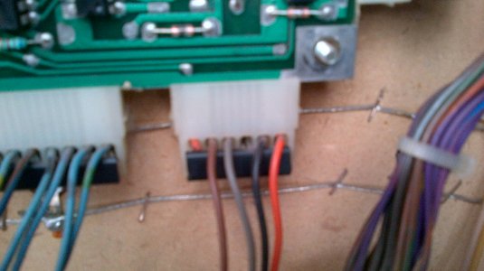
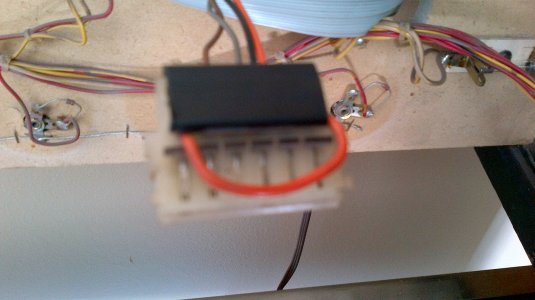
You can use this function on your multimeter tool to check the connectivity of the above mentioned plug for the coin door, by using one lead inside the back of one plug and the other lead on the back of the other, on the same wire. If you have a bad connection, you can usually see it by examining each contact in the plug ends, but sometimes it's more difficult to see with the naked eye, which is what this setting on a multimeter is made to show.
 
Just tried to trip the coin and the credit on the driver board at the pins. I got nothing :(
 
Here are some pics
 

Attachments

  • IMG_00000066.jpg
    IMG_00000066.jpg
    944.8 KB · Views: 270
  • IMG_00000064.jpg
    IMG_00000064.jpg
    888.6 KB · Views: 297
  • IMG_00000069.jpg
    IMG_00000069.jpg
    905.4 KB · Views: 286
And some more
 

Attachments

  • IMG_00000059.jpg
    IMG_00000059.jpg
    614.7 KB · Views: 287
  • IMG_00000061.jpg
    IMG_00000061.jpg
    805.3 KB · Views: 280
  • IMG_00000062.jpg
    IMG_00000062.jpg
    759.6 KB · Views: 266
More
 

Attachments

  • IMG_00000068.jpg
    IMG_00000068.jpg
    904.6 KB · Views: 309
  • IMG_00000065.jpg
    IMG_00000065.jpg
    885.7 KB · Views: 305
  • IMG_00000071.jpg
    IMG_00000071.jpg
    756.8 KB · Views: 277
I too looked up this manual...Odd and just plain wrong that it has no schematic in it...What's a guy to do?
 
Anyone have an extra of any of the following boards....

System 7 Driver Board
System 7 Sound Board
System 7 Display Board

Mark
 
Are they trashed?

If it is a PCB problem, I can give you a link to a place that can help you out, but it may not be necessary. Check the wiring, connector pins and switches with a multimeter set to ohms first. Make a list of each component.

Something like this -

Coin 1 switch test at switch wire solders when triggered
Coin 2 switch test at switch wire solders when triggered
Coin 3 switch test at switch wire solders when triggered

Coin 1 wire from solder to plug contact
Coin 2 wire from solder to plug contact
Coin 3 wire from solder to plug contact

etc.

Basically, what you want to do is check all of the conducting points, starting at the switch and checking each thing separately with the game off, using the multimeter ohm setting so the meter can push it's own current through the switch, wiring and connector pins, to detect continuity.

When you said you tripped the coin/ credit switch, what did you have your meter leads running to?
 
Just going through your pictures, I immediately notice something suspect with one of the plugs, running to one of the boards, pictured in img 061. It looks like one of your wires is completely missing from the head of the plug and another orange lead has been cut, right at the plug.

Can you follow the wiring loom that is running from this plug head back and see if there are any burnt, cut, taped off or missing wires?
 
I jumped a wire to try to trip coin and credit with the plugs off right at the pins. I will check out IMF 61 and let you know
 
General chit-chat
Help Users
You can interact with the ChatGPT Bot in any Chat Room and there is a dedicated room. The command is /ai followed by a space and then your ? or inquiry.
ie: /ai What is a EM Pinball Machine?
  • No one is chatting at the moment.
      Chat Bot Mibs Chat Bot Mibs: Flipper Hermann has left the room.
      Back
      Top