njPinWiz
when you say the jack pins solder connections, what does that refer to? I plan on re-pinning the 9 position Molex connector as soon as the parts come in. Are your referring to the male pins on the board itself, or some other component?
01-28-2016, 08:51 AM
njPinWiz
Another question pinballdaveh...in looking at the board for IC19 and IC17, I could not locate them. I had mentioned that a Rottendog MPU is installed on this machine. Rottendog schematics are provided earlier in the thread. Is there a way (that you know of) to correlated IC19 and IC17 on the old, original boards to the Rottendog? Or, is that really a question for Rottendog tech?
01-28-2016, 08:51 AM
pinballdaveh
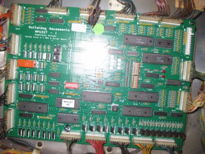
yes the male pins , check for any cracks , and reflow if needed. also can you post a pic of the chip thats just left of the bottom of 2j2?
01-28-2016, 09:31 AM
njPinWiz
2 Attachment(s)
two photos (different exposures) of the lower right portion of the board near jack 2J2. Attachment 6794 Attachment 6795
01-28-2016, 08:52 PM
pinballdaveh
what is the number on the chip that i was asking about , next to 2j2?
01-29-2016, 09:08 AM
njPinWiz
1 Attachment(s)
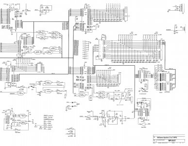
That chip is marked "U17" just under it on the board. Now I am a bit confused & may need to talk to Rottendog. On the schematic they provided (see below, upper left corner), it shows IC17 and IC19 components - but, I can't locate IC17 and IC19 on the board. Seems odd to me. Attachment 6797
01-29-2016, 10:11 AM
njPinWiz
That chip is marked "U17" just under it on the board. Now I am a bit confused & may need to talk to Rottendog. On the schematic they provided (see below, upper left corner), it shows IC17 and IC19 components - but, I can't locate IC17 and IC19 on the board. Seems odd to me. Attachment 6797
01-29-2016, 10:13 AM
njPinWiz
Just checked w/Rottendog...the IC17 and IC19 components were replaced (schematic is out of date) with chip U17. Was only a few bucks so ordered it and will replace on the board. That, along with re-pinning molex connector hopefully will solve things.
02-01-2016, 04:17 PM
njPinWiz
I replaced the U17 integrated circuit on Firepower & it seemed to work initially. All the lanes/switches/targets were activating. Then, a series of odd things began to happen.
The lane change feature didn't work
On ball drain, bonus score registers...then it loads ball in plunger, but even though I had only pressed 1 player, when ball drained it moved to 2nd player, and gave score just as the ball was loaded into the plunger...about 5,000 or 6,000...again, when ball drains it gave player 3 added score, etc.
And upon new ball being loaded in plunger, the upper right kick-out hole activates repeatedly, even tho there is no ball in the hole...it does that until you shoot the new ball out of the shooting lane and onto the playfield.
After further checking, now the inner & outer lanes to the right of the bottom sling do not activate.
Not sure where to go from here, but seems like the problem has gotten worse.....

02-02-2016, 11:32 AM
Coil_Smoke
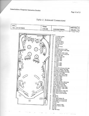
Take a good close look at that kickout hole switch assembly. How is your credit switch supposed to operate? Does it always reset the game during play or will it add players after ball 1. I don't have time to look at switch matrix , is credit switch in matrix? I keep thinking there are shorts, broken connections, possibly intermittent in play field wiring. Try pressing/wiggling everything while switch edges test is active. Could be faulty diodes in your matrix too.
P>S>Sometimes the stiff blades in scoring/activating switches cause problems by making contacts that are not supposed to happen...
02-02-2016, 03:14 PM
njPinWiz
Credit switch when activated always resets the game during play, it only adds multiple players before ball 1. Credit button switch is in the switch matrix: column 1 (grn-brn wire off of 2j2-9 connector) / row 3 (wht-orn wire off of 2j3-7 connector) I'll re-inspect those connections again, and test. Thanks coil!