Data East Jurassic Park (Data East, 1993) Flipper repair help !

Biglots

Pinball Nudger
Joined
Dec 5, 2014
Messages
5
Reaction score
0
Points
2
Favorite Pinball Machine
Jurassic Park
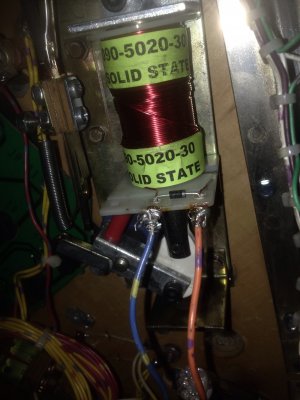
So I'm having issues with a repair. My upper right flipper when out on my Jurassic Park Machine. I check the coil and someone had installed one besides the one in the manual . So I installed a new one from stren that matched the factory one and nothing. So I did a full rebuild on the lower right. Now both are dead. I've checked all the fuses, The wiring diagrams, everything I know or have read to do. Both red light come on on the flipper board when the bottom is pressed. I need some advice on what to check or if I have messed up something. The right upper flipper was intermittent a few months ago then I had the issue where after 10mins of play the machine would freeze. I installed a new power supply and it fixed that problem but the upper never worked since.
 

Attachments

  • image.jpg
    image.jpg
    965.4 KB · Views: 392
have you checked the under-side of the flipper board for any cracked solder connections? does any parts on the flipper board look bad or burnt?
 
Board check

The board looked okay no burnt spots. The F1 fuse which controls the right lower flipper was blown. I replaced it still nothing and now the new fuse is looking discolored. The upper right flipper idk why it went out, all I did on the lower right was put in a new coil and rebuild kit then it stopped working. What should I look for that is causing the fuse to blow?Thank you for replying so fast I really want to be able to repair this.
 
there isnt any manual for jurassic park availible from PDB to download so i found a manual from TFTC that also has 3 flippers and the flipper board schematic and downloaded that. of what i see the left flipper has 1 flipper button switch and 1 EOS switch on the flipper assembly, the right flipper has 2 flipper button switches and 1 EOS switch. the flipper button switches and the EOS switches are flipper board inputs, and dont get wired directly to the flippers. each flipper coil is fused and driven by the flipper board outputs. each flipper has a LED that lights on the flipper board when flipper buttons are pushed, 1 for left and 2 for right. the manual talks about EOS switch theory, these switches are gold point switches and should not be filed, but should be clean and adjusted properly. if all the flipper coils have the same part number and the left flipper is working correctly, coil swapping from left to right flippers may be possible to see if the problem moves and to verify that the coils are not the problem. if IDC female connectors are used in your machine they need to be checked for loose wires or connections on the flipper board. there may be driver transistors on the flipper board that are weak or bad thats causing the fuse to blow when the flipper coil load is applied or driven.
 
Okay so I checked the lower right with an ohm meter and it was only 0.2. I took it off and placed the old one back on. I also flipped the diode on the upper right coil, someone said it was backwards and it was from the old one and all the others. I replaced both fuses on the flipper board for those flippers. Powered up the machine went to service mode. The lower right instantly flipped once, then nothing. I checked both fuses were blown. Any ideas on where to look now?
 
what is the fuse #s that are blowing ? ex F1,F3,F5 ? how are your circuit board parts testing and de-soldering, soldering skills ? chances are there is shorted transistors on the flipper board. do you have the wires and diodes on the flipper coils correct now?
 
F1

Its the F1 and F5 that are blowing. My skills on soldering small boards is near non, I have some stuff I can practice on though.
Yes I have tested the resistance on all the coils and the diodes match how the old ones were with the others with the band on the black/yellow wire which looks like the one coming from the board. How would I go about testing the transistors? I don't mind getting a new board but I don't want to install one to only mess it up.

Thanks for your help too!!!
 
the pasts that need to be checked for F1 are D1 , Q2 , and Q3. the parts for F5 are D11 , Q15 , and Q16. D1 and D11 are 1N4004 diodes. Q2 and Q15 are TIP32 transistors. Q3 and Q16 are TIP36C transistors. after removing the flipper board from machine take a pic of it for a visual aid in helping re-installing the parts back in proper direction. i dont know what kind of soldering was used for the coil soldering , but a 25 or 30 watt iron is needed for board work. also a roll of desoldering braid is needed( availible from radio shack ) . to properly test parts they need to be unsoldered and removed from board or other parts on the board might give a false reading. unsolder and remove parts one at a time and watch were the white band on diodes and metal tab on transisters direction in were they came out to re-install them in the proper direction. tape each part to a paper but not covering leads and mark the paper with each part #. test diodes in each polarity direction , 1 small resistance reading in 1 direction is correct. testing the transistors put one test lead on the center lead and the other test lead to each of the outer leads. next use the other test lead to the center lead and repeat process. 2 low resistances readings is correct. open or shorted parts need to be replaced. solder back in good tested parts in the direction that they came out. all parts are availible from marco. the part # for the complete board is 520-5033-03 $89 is also availible from marco
 
williams WPC and data east power supplies look similar if not the same. the 5vdc problem that cuts out when the machine is on a while is a cap going or already bad . on data east its C2 electrolytic cap 100 UF ( not sure on the williams part #). this part is availible from radio shack part# 272-1028. thic cap does have polarity so it must be installed correctly. when looking at it on the board it may not look bad , but it may be leaking from underneath. sometimes this caps leaking acid will cause trace damage on the board. so if it hasnt been changed yet it should be anyway. pick 1 up when you get your desoldering braid. retest power supply board when repaired and see if it cuts out.
 
New problem

I have the soldering gun I got one a few months ago so I could learn hoe to do this. I went be radio shack and picked up the supplies you said to get. Also my new flipper board came in today. I installed it and flippers were back to normal. So I'm going to use an old pc to practice on then try and repair my old flipper board.
The other problem now which was here before, is I get a 1 ball missing error the game tties to shoot a ball and can barely get it out the shoot. The coil reads right. I can see that you need to be good at reading scimatics and soldering boards to owe pinballs.
 
Damn, switch matrix shows 7 trough switches. That game definately has got balls(6?). The ball assembly looks like six switches that count balls and the last switch on the right is in position to detect ball at shooter. That shooter looks like a simple straight on ball kicker or V.ertical U.p K.icker (On It's Side?). I would start checking the left most switch #9 and diode for proper function. Switch diagnostics should show the state of those switches.
 
Last edited:
along with switches 9-14 the 6 outhole trough switches, the captive ball switches need to be checked also ex. switch 59 T-REX trough and switch 60 right scoop trough. the ball missing code and the ball kicker not kicking the ball up to the shooter lane properly might be switch 15 trough #7 right. this switch is a micro switch and if not adjusted properly and not working properly it might not let the ball to properly position itself by centering it on the shooter plunger. if the ball isnt centered properly it wont get the full kick from the plunger. it seems like these micro switch problems were eliminated with the use of opto trough switches. taking apart the ball kicker and cleaning the sleeve and plunger , and checking the plunger tip for mushrooming might help. change plunger if needed.
 
General chit-chat
Help Users
You can interact with the ChatGPT Bot in any Chat Room and there is a dedicated room. The command is /ai followed by a space and then your ? or inquiry.
ie: /ai What is a EM Pinball Machine?
  • No one is chatting at the moment.
      Chat Bot Mibs Chat Bot Mibs: qinnuendo has left the room.
      Back
      Top