Found a site which may help you out:
http://www.pinrepair.com/em/
faralos said:
PLEASE make sure the thing is unplugged and there is no residual power left on the board!
Listen to faralos. A dodgy power supply is nothing to mess with. He's also right in that the flipper solenoid is drawing too much current.
Oh, and just in case you haven't read the article(s) above yet - DON'T LUBRICATE ANYTHING!!!!! Especially the solenoid rods. Throw that WD-40 aside - you'll likely set fire to your new acquisition.
It looks like early pinnies used 6V AC to power the lights and 24-30V AC to power the solenoids. NO DC! This surprised me, but does simplify the power supply a lot.
Out of all the components, though, the transformer is likely to have weathered the age better, provided the primary coil winding insulation has held up. The primary is more vulnerable as it is exposed directly to mains voltage and inrush current when switched on (and then again when the electric field and induced magnetic field in the core collapses as it is switched off).
[EDIT] The author above concurs - he says out of ~300 pinnies he's fixed, only one had a bad transformer, and it was a melted blob of goo.
faralos said:
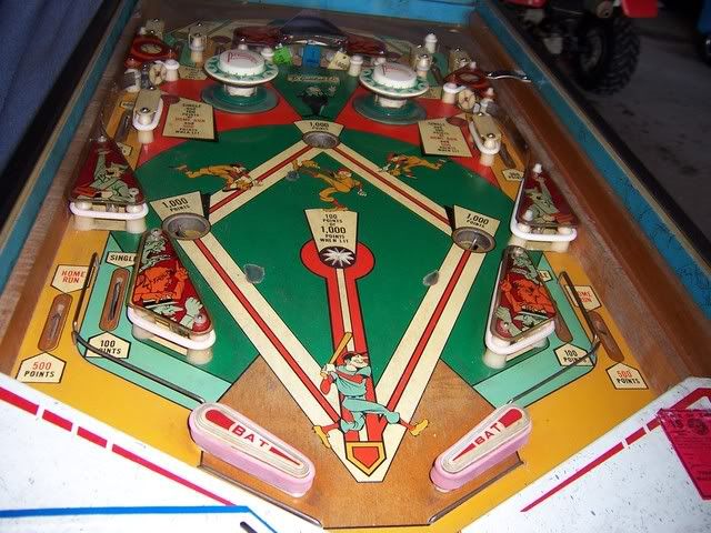
Does it even have a board or is it all just switches underneath with relays? Depending on how old it is you may not even have any circuit boards in it at all.
teamhex said:
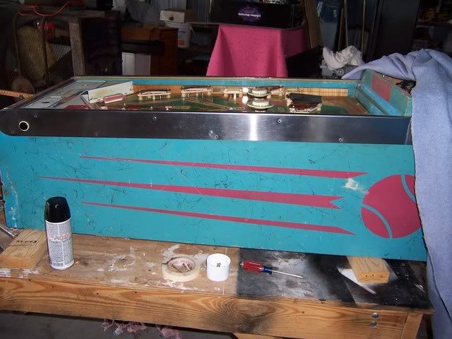
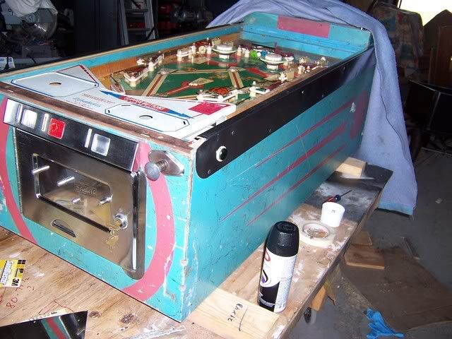
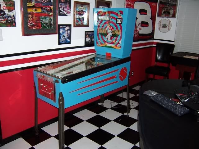
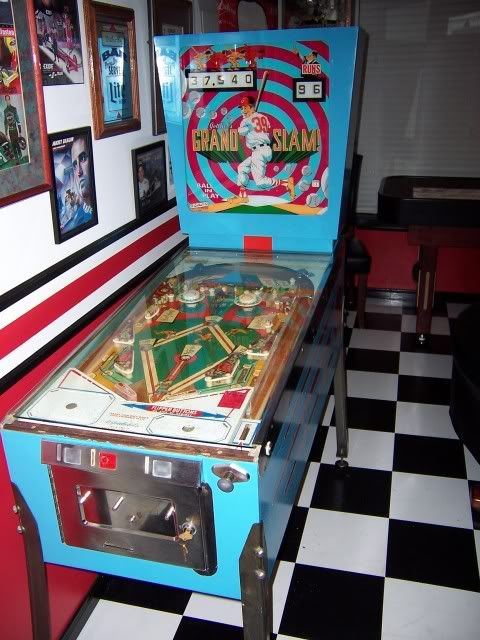
Its from 72 man, from what I can see, its a ton of relays and contact switches. A transformer and tons of other random things.
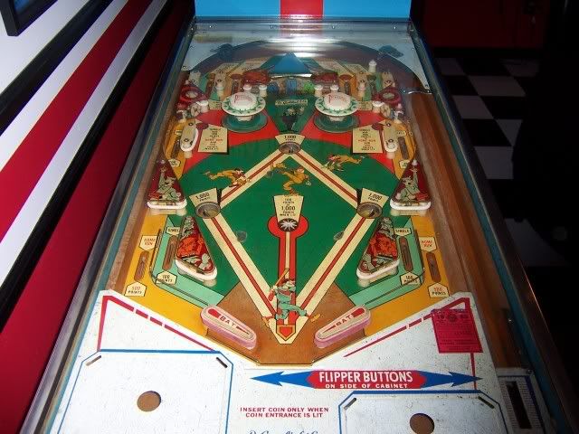
Sounds like the underside of the playfield
is the board. So where, then, is the transformer and other power supply components? At the rear on the bottom of the cabinet?
In those days things were built to last much more so than today, but solenoids are particularly vulnerable because they move.
None of it is random - everything was carefully put there for a particular purpose. I think you have established that the switches and relays work - they're the least of your troubles.
Lets not forget that 3 years before that thing was made, the same generation of components sent people to the moon and back several times. Apollo 11 almost failed to return because Buzz Aldrin broke off the switch controlling the pyro-bolt which separated the lander and return capsule with his backpack on the way out the door (must have been a
really fun moon walk - they were later saved by a NASA pen which just fit in the switch hole allowing them to close the circuit), and 13 because the wrong size bolt was installed in an oxygen tank stirrer - human error each time. Military spec components were used, but they still aren't a whole lot better than industrial spec, and your pinball machine never had to survive a space launch or mach2 at 100,000 feet!
elton said:
and I just thought it was the noises in my head! :grin:
Ha! Elizabeth Taylor swears she could hear voices due to the fillings in her teeth when she drove past a local radio transmission tower. Unfortunately there's nothing to provide anything like a tuned circuit in dental amalgum and unconductive bone like teeth....
phoenixx said:
Teapots on electrical stoves, but then i think many things would do that if the circumstances are right,...
Love the teapot story, and I'm sure it happens from time to time - but without an amplifier you'd have to be pretty bloody close to the transmitter and in a very quiet place. I wonder if changing the amount of water in the kettle allowed her to change channel!
My friend built a crystal set and it's loud and clear with a matched impedance earpiece, but through an 8 Ohm speaker you could barely hear it (but you could hear it).
teamhex said:
My dad was saying he thinks the transformer may not be giving full power in each rail.
Please clarify. What voltage rails are available - 6VAC and 30VAC?
If you have the manual and circuit diagram - attach them here and give us a squiz. Also need to know your mains voltage and frequency if it's not on the diagram.
Also - where are you at? What has changed that the flipper doesn't buzz anymore and the 'staged' failure no longer occurs?