cass2024
Pinball Player
- Joined
- Jun 20, 2024
- Messages
- 21
- Reaction score
- 21
- Points
- 9
- Favorite Pinball Machine
- panthera
Hello Pinball Lovers,
Myself and 3 other students are taking our final term in an Electronics Engineering Technologist diploma in British Columbia, Canada. We have a final Capstone project where we showcase the skills we have acquired throughout the program. As you may have already guessed, our project is to rebuild an old Gottlieb Panthera pinball machine!
The machine had been previously worked on as a project back in 2007. It had original MPUs and driver boards removed and replaced with their own design. Panthera was running a PinMAME ROM via an old brick of a laptop and used ethernet connections between the laptop and other PCBs. In its current state, the machine did not work. So we've decided it needs a new breath of life!


Our objectives of the project are as follows:
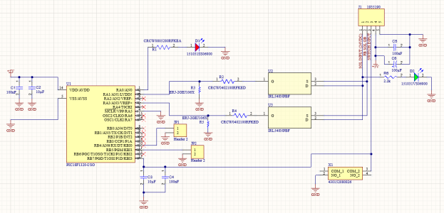
- Replace PCBs with LISY80 and our own driver board
- Run MPF software on Raspberry Pi Zero via LISY80 board
- Replace VFD Displays with 7-seg LED displays
- Replace speaker and include original game sounds
- Retain original look and feel of Panthera
All hardware for the playfield is original with the exception of the lights, which have been replaced with LEDs. As we wait for some components to get the LISY80 board up and running we have been doing our best to map and test equipment. All solenoids and LEDs have been tested and confirmed to work properly.
Our biggest hurdle at the moment is documenting the wiring from the original board. I have included another post about the lamp assignments here: https://pinballnirvana.com/forums/threads/cable-connector-wire-assignments-help.23247/
My hope is that we can start mapping the wires out by testing them through the LISY one at a time but until we have that up and running we will continue to research, trace wires, and scour the internet for any documentation.
We plan to maintain this thread for the duration of the project, and will continue to update as we go. Wish us luck!
-Capstone Crew
Myself and 3 other students are taking our final term in an Electronics Engineering Technologist diploma in British Columbia, Canada. We have a final Capstone project where we showcase the skills we have acquired throughout the program. As you may have already guessed, our project is to rebuild an old Gottlieb Panthera pinball machine!
The machine had been previously worked on as a project back in 2007. It had original MPUs and driver boards removed and replaced with their own design. Panthera was running a PinMAME ROM via an old brick of a laptop and used ethernet connections between the laptop and other PCBs. In its current state, the machine did not work. So we've decided it needs a new breath of life!
Pictures of old project PCBs and wiring
Our objectives of the project are as follows:
- Replace PCBs with LISY80 and our own driver board
- Run MPF software on Raspberry Pi Zero via LISY80 board
- Replace VFD Displays with 7-seg LED displays
- Replace speaker and include original game sounds
- Retain original look and feel of Panthera
All hardware for the playfield is original with the exception of the lights, which have been replaced with LEDs. As we wait for some components to get the LISY80 board up and running we have been doing our best to map and test equipment. All solenoids and LEDs have been tested and confirmed to work properly.
Our biggest hurdle at the moment is documenting the wiring from the original board. I have included another post about the lamp assignments here: https://pinballnirvana.com/forums/threads/cable-connector-wire-assignments-help.23247/
My hope is that we can start mapping the wires out by testing them through the LISY one at a time but until we have that up and running we will continue to research, trace wires, and scour the internet for any documentation.
We plan to maintain this thread for the duration of the project, and will continue to update as we go. Wish us luck!
-Capstone Crew